A lot of people aren’t aware that you can 3D print transparent parts. I should say that this material is semi-transparent, although there are some tricks to make it more transparent.
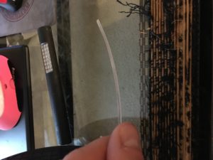
First, this is the filament itself.
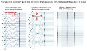
As you can see, the filament itself is clear. The issue of transparency on a printed part come into play due to how the layers line up. I will borrow this image from Taulman3’s website:
Let me explain this diagram a little. The left side shows “standard layer” settings on a 3D printer. Let’s say you have nozzle diameter of 0.4mm. If you set up your printer with standard layer thickness, you would have the layer height set at 0.2mm. In a simplified, close-up view of a cross section of the print, it would look like the left size. Basically, the printer is putting down tubes of material that are 0.4mm in diameter, but because the printer is making the next layer only 0.2mm higher, it has to “squish” the tube into an oblong that is 0.2 high. The advantage of this set up makes the layers bond together more, due the larger contact area between layers.
The effect of this on the optics is the internal reflections of light as shown in the diagram. The more reflections, the less clear the image will be on the other side.
The middle part of the diagram shows a print that has a layer height of 0.4mm. In this situation, there is essentially no squishing of the tube. As a result, the light enters and exits the material with less internal reflections, which leads to a clearer image. The downside is that there is less contact area between layers, and the part will be weaker.
Finally, the right side of the diagram shows a special secondary step after printing that make the part very clear (it involves applying a coating). Read the article from Taulman for an explanation of this step. The main take way from this part of the image is that this coating allows the light to pass through directly without reflections.
One caveat about this diagram: All of this is based on 1 perimeter layer of the print. Most applications will not allow only 1 perimeter layer. In the left part of the diagram, this would be a wall thickness of only 0.6mm. And with the middle part, it would be a wall thickness of only 0.4mm. This is very thin and for most applications the part will break.
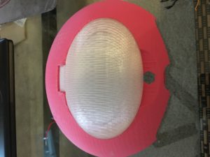
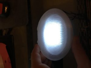
Below is a prototype I am working on for a client. I cannot go into what the product is, but for the sake of this article, this image is a top hinge with a clear window.
As you can see, it is not full transparent. I used a layer setting of 0.2mm to make the part stronger and I made the wall thickness 2.54mm thick. Whenever designing, there are always tradeoffs.
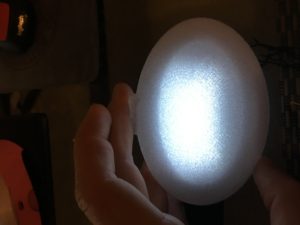
I discovered the orientation of the print greatly affects the clarity. Compare print 1 to print 2
Print 2
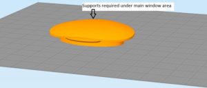
Print 1 was oriented as shown here
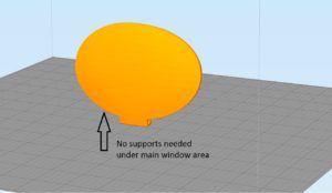
In this setup, support material was required underneath the main window area. Because of this, it roughened up the surface and make the window more opaque. I then tried the part in orientation 2, shown below.
This direction did not require any supports directly on the main surface. As a result, a clearer part was produced.
I hope this article shows you some settings and factors involved in running Tglase. The future of 3D printing is very exciting as more materials like this get developed. It really opens the possibilities of what products can be made through 3D printing.


