This week’s blog post is on a recent project where the client needed a stylish base to hold glass awards. These were being handed out at his company’s annual party for leadership.
The awards are shown the following pictures.
This project was done using the sheet metal functions in SolidWorks. When using sheet metal, it is important to make sure you get the bend angles and cuts calculated correctly.
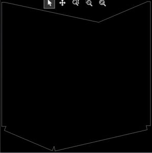
After designing the 3D file shown, we moved onto the DXF cut pattern. This file is used by the plasma cutter to cut the raw stock sheet metal (if you don’t know what a plasma cutter is, watch this video for an example https://www.youtube.com/watch?v=9UNELVs745s). Here is a picture of the DXF files. It is basically a map of where the plasma cutter travels.
Cut Pattern for Sheet Metal
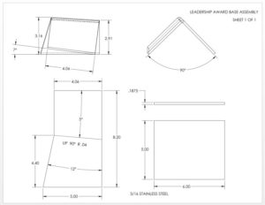
Finally, we made the 2D drawings to show the bend angles and where to weld the parts together. Here is a picture of the 2D drawing.
This was a fun project because the shapes were a little different than your typical sheet metal project (like making rectangular boxes and enclosures)
Do you have a design project requiring sheet metal design or have questions about it? You can reach us by emailing info@caddesignhelp.com


