Reverse Engineering Blog post
Reverse Engineering (RE) is the reproduction of another manufacturer’s product following detailed examination of its construction or composition. This could apply to physical products or digital (like software), but this article is going to focus on the physical products side.
Why would someone want to reverse engineer something? Could be many reasons but a few that come to mind:
- Find out how a product work
- Copy an existing product to sell it or improve upon it
- Replacement parts for something that broke (like a car part that broke and there are no replacements available)
And there are probably more reasons than that.
The best way to explain how something is reverse engineered is to give some examples. Before I do that though, the 2 main methods I use to reverse engineer are
- Caliper measurements
- 3D Scanning
There are advantages and disadvantages to each. The advantage of caliper measure is that it is less expensive, and you can fix “mistakes” in the part as you work. The disadvantage is accuracy and time consumption is higher. The advantage of 3D Scanning is the high level of accuracy. The disadvantage is the cost (the scanner itself is tens of thousands of dollars), and when the scan is done there a lot of cleanup work to get a final useable file.
Next, we will look at examples of products that I reverse engineered.
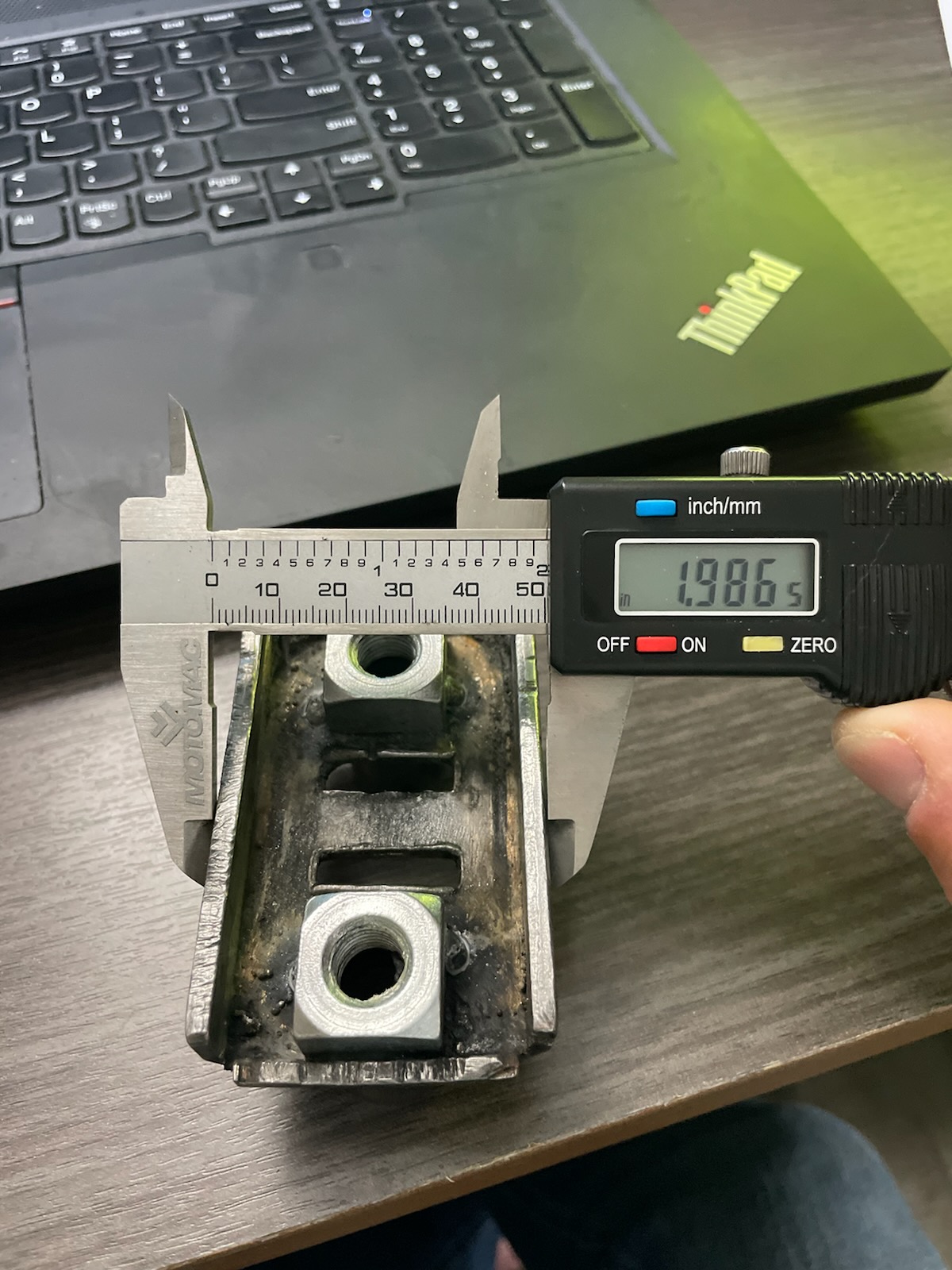
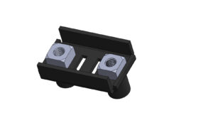
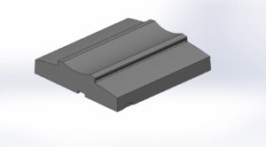
- First part up is a metal part named part 4296. This part was made from sheet metal with 2 nuts welded to it.
The first picture shows the actual part (with calipers set up) and the 2nd picture shows the completed cad file.
As you probably guessed, I reverse engineered this part by measuring with calipers. The first reason I chose calipers is because the part is pretty much rectilinear. What this means is that there are not any complex curves on the part. The second reason I chose calipers method is because of all the damage. With all these cuts and bumps, the scanner would have picked all that up and it would have been a serious challenge to then repair all of that in the scan.
- 2. LS Manifold Engine
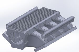
This part is a complex engine manifold. It is about 18 inches in length and weighed 100+ pounds. For this project, the only way to do was with 3D scanning.
Because of all the internal channels and complex geometry, it would be literally impossible to make this by using calipers. Anytime you have complex curves going in 2 different directions, its too complicated to try to capture this by any other method than 3D scanning.
This scan was also complicated because it had to be scanned on the outside and then scanned on the inside separately, with the 2 scans then spliced together. This was a very involved project to say the least.
- Computer Housing Cover
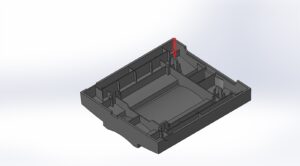
This is a top housing of a special desktop computer. This is a project that could have gone either way. The part is basically in perfect shape so a scan would have worked fine. It is also black which is an ideal color for a scan. If a scan is reflective or transparent it can lead to problems collecting the data. One way around that is to spray the part with a white powder.
In any case, I decided to use calipers here due to the amount of surface matching work I would have needed to capture all the ribs.
This part is manufactured by injection molding. Injection molds require draft on all the surfaces that are not perpendicular to the parting line. The draft angle is usually a round number, like 1 or 2 degrees. The way to figure it out is to take a thickness measurement at the top of a rib, and then at the bottom. This is shown by the red arrow in the next photo.
- Medical Foam
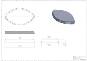
This product is a piece of foam that goes into a knee brace for a medical application. I chose caliper method for this product.
Because this product is flexible, scanning it could be an issue. Most of the time when you reverse engineer a product, you want the product to be modeled in its manufactured state (like how it will come out of the mold). After this part is molded, it is put into a knee brace, and it becomes bent. The piece that was sent to me was a piece that was already used. Therefore, if I had scanned it, the scan would have shown the flexed part. If I had a fresh part from the mold, I could have scanned it.
I created accurate measurements by holding the part flat and tracing it on paper. I then scanned (on a regular paper scanner) the piece of paper and used sketch picture in Solidworks to scale the photo to the correct size. It was a relatively simple process from there in Solidworks. I chose to use a loft to create the body but I could have also used extruded boss with a draft on it to also accomplish the same result. The picture above shows the 2D dimensional drawing of the part.
- Front headlight housing for car
Typically, most car parts have complex curves. So, this is another case where 3D scanning makes the most sense.
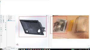
This is a metal housing for the front headlights on a car (a General Motors car of some type if I remember right). The back curvature is way too complex to accurately measure by calipers. Additionally, the screw mounting hole locations are critical on a part like this. If those are off by more than 1mm, it is unlikely that the part will fit in the car.
It is interesting to note that the raw scan produces a file as you see on the left side of the previous photo. The surfaces are “patchy”. This is because the part has not been “idealized” yet. All manufactured products have flaws and the scanner captures all that. To make it simple, lets assume that the outer edge perimeter of this was meant to be perfectly flat. Unless it was (which it will never be), the scanner will pick up the surfaces as slightly odd angles to the next surface. That’s why you see all those patches that look like a spider web. The challenge at this point in the project is to create the “average” of these surfaces so that it is a flat outer edge perimeter. When the project is done it will look like a file drawn natively in Solidworks.


