Optimizing design to save material and 3D print time
I recently designed a motor housing for a portable vacuum cleaner. This required fitting together many pieces. What I want to show in this article is how I designed this to optimize for material and 3D print time.
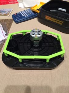
First, I want to explain the goal of these parts. The motor assembly is shown in Figure 1. The green part was a test print to verify the screw locations were measured correctly.
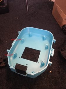
Figure 2 shows the motor housing and the posts (red arrows) is what holds the motor assembly.
The important thing to mention about this part is that I printed it in the orientation shown in Figure 2. By printing it this way, I was about to make it with almost no support material. For reference, this is the bottom of the motor housing.
Now if we look at the top of the motor housing (Figure 3), we can see a few more features. The orange arrow points to a small indentation. The black piece next to it (the battery connector) fits into this slot. See Figure 4. I used super glue to hold the battery connector in place.
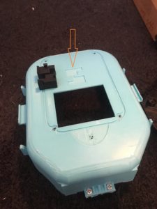
Figure 3.
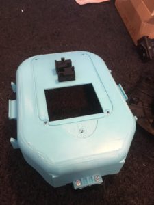
Figure 4.
The battery connector and slot were designed so that the connector would only fit in one orientation. This is a good design strategy as it prevents accidental backwards installation. Figure 5 shows the battery. The battery is installed with the blue arrow part pointing down.
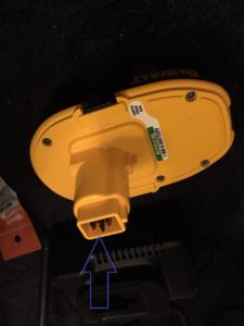
Figure 5.
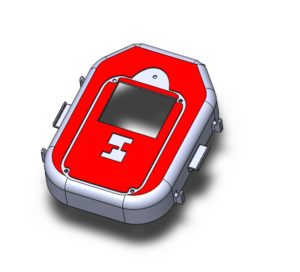
Now for the main conclusion of this post. Had I made the battery connector permanently connected to the motor housing, there would have been a large amount of support removal. Essentially the entire upper side of the motor housing would have needed support (all the faces in red). See Figure 6. By making this design multiple pieces, I was able to save a lot of time and material.


