Visit to Strategic 3D solutions in Raleigh
I recently went to Strategic 3D solutions in Raleigh to try out 3D scanning. I brought a battery that I had previously reverse engineered using calipers (meaning, I took measurements to build the CAD file). 3D scanning is another way to reverse engineer a part. I wanted to see how hard and complicated 3D scanning is compared to the more traditional caliper method. Now that I have the scan data (point cloud data), I have to use some more software to create the actual CAD data. The following information explains what is going on.
Strategic 3D utilizes the Geomagic Capture 3D scanner along with the Design X software to do 3D scans. This is not the only method out there but this is what they use.
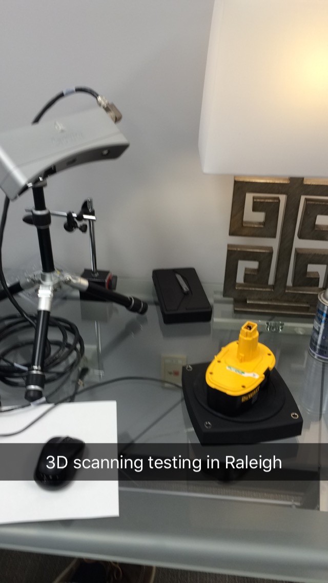
1. The first step was to set up the part (this black/yellow 18V Dewalt Battery) on the rotating platform to get the first scan. At a minimum 2 different orientations of a part will be required on any 3D scan (so you can capture the geometry on the bottom). See photo Scan 1.
Scan 1
When the scan starts, blue light is shot at the part and the reflection back creates what is a called a “point cloud”. Each point is a location in space. These locations are determined using “trigonometric triangulation” This data is captured on the computer screen. For more information on this, please see this link:
http://www.rapidform.com/3d-scanners/
The “video of first scan” shows the scan in progress.
Video of First Scan
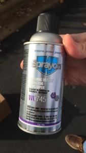
2. What we found out was that the black color did not reflect well enough. There is a solution to this. The solution is to spray the part with a white coating. In this case, we used Spray On Welding Defect Detector. See photo “Coating” and “Video of Coating”.
Coating
Video of Coating
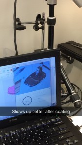
3. After coating, we scanned again. See photo “scan 2, after coating”. The image is now showing up great on the computer.
Scan 2, after coating
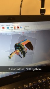
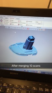
4. The scanner takes a photo and then turns the plate a little each time and takes a new photo. What it is doing is taking many images, and then matching them up based on key features. The photo “first 2 images of scan after coating” shows the result of two images. The photo “merged scan result” shows how the scan is looking after merging 10 images. With only 1 or 2 images, you will often have “holes” in the part, which lead to issues later on. This is why many images are taken. You can see the holes if you look closely at “first 2 image of scan after coating”.
First 2 images of scan after coating
Merged Scan Result
5. This process had to be repeated one more time, with the part turned onto a different side. This is because the first series of scans could not capture the bottom.
6. Now that the scanning is completed, the point cloud data is finished. The next step is to combine these points in space to create the solid model. Special software is needed to do this, so that is my next goal. After I have used this software, I will make an updated blog post to describe my experience.
For an idea of the effort so far, it took around one hour to 3D scan the battery. I am not sure how long the software part will take. I was able to reverse engineer this battery using calipers in 8 hours, accurate to within 0.4mm.


